Test name
dy_devo5
Calculation type
MECHANICS DYNAMICS 3D
TRANSIENT RESPONSE
Finite element type
POUT
Topic
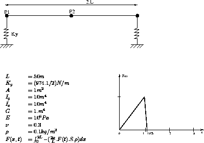
Transient response of a supported beam.
The beam is simply supported by elastic supports.The triangular distributed load has its amplitude as a function of time. The problem consists in finding the maximum deflection for different moments.
Goal
Find the maximum deflection of the beam.
Reference
Walter C. Hury and Moshe F. Rubinstein : Dynamics of structures (Englewood Cliffs : Prentice-Hall, Inc., 1964) p.294.
Version
97' customer version
Model description

Test dy_devo5 Results
Results

CASTEM figures

*         Test Dy_devo5.dgibi: Jeux de données        *
*         ------------------------------------        *
*                                                     *
GRAPH='N';
SAUT PAGE ;
*******************************************************
*  REPONSE TRANSITOIRE D'UNE POUTRE -METHODE MODALE
*******************************************************
*
* DESCRIPTION DU PROBLEME
* -----------------------
*
* UNE POUTRE EST MONTEE SUR DES APPUIS ELASTIQUES .
* SUPPOSANT UNE CHARGE REPARTIE TRIANGULAIRE AVCE UNE
* INTENSITE VARIABLE DANS LE TEMPS, ON CHERCHE A
* CALCULER LA FLECHE MAXIMALE EN DIFFERENTS INSTANTS.
*
* REFERENCE :
* ----------
*
* WALTER C. HURY AND MOSHE F. RUBINSTEIN,DYNAMICS OF
* STRUCTURES, (ENGLEWOOD CLIFFS: PRENTICE-HALL,
* INC.,1964),P.294
*******************************************************
OPTION  ECHO 0 ;
OPTION DIME 3 ELEM SEG2 ;
*
*  MAILLAGE
*
 P1 = 0. 0. 0. ; P2 = 50. 0. 0. ;
 L1 = D 4 P1 P2  ;
*
* MODELE
*
 MOD1 = MODELE L1 MECANIQUE ELASTIQUE POUT ;
*
*  CARACTERISTIQUES MATERIELLES ET GEOMETRIQUES
*
 MAT1 = MATER MOD1 YOUN 1.E6 NU 0.3  RHO 0.1 ;
 CAR1 = CARAC MOD1 SECT 1 INRY 10. INRZ 10. TORS 1.
  VECT (0. 1. 0.)  ;
*
*   CONDITIONS AUX LIMITES : APPUI ELASTIQUE
*          ET CONDITIONS DE SYMETRIE
*
  K = 974.1 / 2  ;
 CL1 = APPUI UY K  P1  ;
 CL2 = BLOQ L1 RX RY UX UZ ;
 CL3 = BLOQ P2 RZ    ;
 CLTOT = CL1  ET CL2 ET CL3 ;
*
*  MATRICE DE  RIGIDITE
*
 RIG1 = RIGIDITE MOD1 (MAT1 ET CAR1 ) ;
*
*  MATRICE DE MASSE
*
 MAS1 = MASSE MOD1 (MAT1 ET CAR1 ) ;
*
*  CALCUL DES MODES
*
 TAB1 = VIBR  'INTERVALE' 0. 5.
   (RIG1 ET CLTOT) MAS1   'TBAS'  ;
TAB2 = TAB1.MODES ;
NNOR TAB2 AVEC (MOTS UY ) ;
NMOD = DIME TAB2  - 2 ;
IB = 0 ;
 REPETE BOUC NMOD ;
  IB = IB + 1   ;
  F1 = (TAB2.IB).'FREQUENCE'  ;
  OMEG1 = (F1 * 2.) * PI ;
  SI (IB 'EGA' 1 ) ; OMEG1TH = 7.155 ;
  SINON ; OMEG1TH = 28.23   ; FINSI ;
 ERR1 = ((OMEG1 - OMEG1TH) / (ABS OMEG1TH)) * 100. ;
MESS
'MODE 'IB 'THEORIE 'OMEG1TH'CASTEM 'OMEG1 '%ERREUR '
 ERR1 ;
  DEP1 = (TAB2.IB).DEFORMEE_MODALE ;
  DEF1 = DEFORM DEP1 L1 1. ROUG ;
  DEF0 = DEFORM DEP1 L1 0.  ;
  SI (NEG GRAPH 'N');
    TRAC (0 0 10000)(DEF0 ET DEF1)  ;
  FINSI;
 FIN BOUC  ;
*
TABM = TAB1  ;
*
* --  PREPARATION DES DONNEES POUR L'OPERATEUR DYNE
*
*
* CHARGEMENT
*
*
*  FORCE REPARTIE
*
 FC1 = COOR 1 L1 ;
 FC2 = (FC1 / -50.) * 2. ;
 FC3 = NOMC FC2 UY ;
 MODB = MODEL L1 MECANIQUE ELASTIQUE BARR ;
 MATB  = MATER MODB SECT 1. RHO 1. ;
 MASB  = MASSE MODB MATB ;
 FC4 = MASB * FC3  ;
 FC5 = EXCO FC4 FY FY ;
LI1 = PROG 0.  1.  1.025  3.0 ;
LI2 = PROG 0.  1.    0.  0.  ;
EV = EVOL MANU T LI1 F(T) LI2 ;
CHA1 = CHAR 'FORC' FC5  EV ;
TABCHAR = TABLE 'CHARGEMENT' ;
*
*   PROJECTION SUR LA BASE MODALE
*
CHA2 = PJBA CHA1 TAB1 ;
TABCHAR.'BASE_A' = CHA2  ;
*
*  TABLE DE SORTIE
*
 TABSOR = TABLE 'SORTIE' ;
 TABVAR = TABLE 'VARIABLE' ;
 TABSOR.'VARIABLE' = TABVAR ;
 TABVAR.'DEPLACEMENT' = VRAI ;
 TABVAR.'VITESSE' = FAUX   ;
 TABVAR.'ACCELERATION' = FAUX  ;
*
* APPEL A DYNE DE_VOGELAERE
*
TABRES =
DYNE DE_VOGELAERE TABM TABCHAR TABSOR 80 0.025 1 ;
*
*  RECOMPOSITION POUR LES TEMPS 1.45 ET 1.9
*
DEP1 = RECO TABRES TABM 1.45 'DEPL'  ;
DEP2 = RECO TABRES TABM 1.9 'DEPL'  ;
*
*  COMPARAISON AVEC DES RESULTATS ANALYTIQUES
*
 FLECH1 = EXTR DEP1 P2 UY  ;FLECH1TH = 0.23382   ;
 ERR1 = (( FLECH1 - FLECH1TH) / (ABS FLECH1TH)) * 100.;
MESS '    FELECHE MAXIMALE  T = 1.45       '  ;
MESS'THEORIE   'FLECH1TH'CASTEM  'FLECH1'%ERREUR 'ERR1;
*
 FLECH2 = EXTR DEP2 P2 UY  ;FLECH2TH = -0.24283   ;
 ERR2 = (( FLECH2 - FLECH2TH) / (ABS FLECH2TH)) * 100.;
MESS '    FELECHE MAXIMALE  T = 1.9      '  ;
MESS'THEORIE   'FLECH2TH'CASTEM  'FLECH2'%ERREUR 'ERR2;
*
SI ((MAXI ABS (PROG ERR1 ERR2)) < 5);
ERRE 0;
SINON;
ERRE 5;
FINSI;
FIN ;
Test dy_devo5 Comments
NNOR TAB2 AVEC (MOTS UY ) ; The NNOR instruction norms the object TAB2 so that the greatest value equal 1. The keyword AVEC limits the research only to UY component.
FC1 = COOR 1 L1 ;
FC2 = (FC1 / -50.) * 2. ;
FC3 = NOMC FC2 UY ;
MODB = MODEL L1 MECANIQUE ELASTIQUE BARR ;
MATB = MATER MODB SECT 1. RHO 1. ;
MASB = MASSE MODB MATB ;
FC4 = MASB * FC3 ;
The distributed load is created by the multiplication of the load FC3 (which
is a CHPOINT) by the mass matrix MASB. This method allows to balance the load
in the meaning of finite elements.
TABCHAR = TABLE 'CHARGEMENT' ;
CHA2 = PJBA CHA1 TAB1 ;
TABCHAR.'BASE_A' = CHA2 ;
The PJBA operator projects the load CHA1 onto the modal basis TAB1.
The projected load CHA2 is put in the table TABCHAR of CHARGEMENT subtype
and indexed by BASE_A. The A-basis is the modal basis in which the
equations are uncoupled.
* OUTPUT TABLE
**
TABSOR = TABLE 'SORTIE' ;
TABVAR = TABLE 'VARIABLE' ;
TABSOR.'VARIABLE' = TABVAR ;
TABVAR.'DEPLACEMENT' = VRAI ;
TABVAR.'VITESSE' = FAUX ;
TABVAR.'ACCELERATION' = FAUX ;
It is necessary to define the output table and its subtype :
the TABSOR table of SORTIE subtype defines the data to be saved during the
use of DYNE operator.
TABSOR.VARIABLE is a table too, its subtype is VARIABLE.
In this example, only the displacements will be saved because the content
of the boolean variable (TABVAR.'DEPLACEMENT') is true and the content
of the other boolean variables (TABVAR.'VITESSE' and TABVAR.'ACCELERATION')
is false.
TABRES = DYNE DE_VOGELAERE TABM TABCHAR TABSOR 80 0.025 1 ;
- The TABM table contains the modal basis.
- The TABCHAR table contains the evolution of applied free forces (which are
projected onto the modal base).
- The TABSOR table defines the results requested in the TABRES table.
- The number of steps is 80, the value of time step is 0.025.
- A result is saved every 1 computation step.
- TABRES contains the results of the computation.
The maximum value of time step is about one tenth of the smallest period of the used mode shapes.
The TABRES subtype is RESULTAT_DYNE.
- TABRES.'TEMPS_DE_SORTIE' contains the list of output times.
- TABRES. i is a table containing the results of the  output step.
The indices of TABRES. i depend on the requested variables given previously
in TABVAR. Here we will find only the DEPLACEMENT index.
TABRES. i .DEPLACEMENT is an object of CHPOINT type which component is ALFA
because the computation was done in A-basis.
DEP1 = RECO TABRES TABM 1.45 'DEPL' ;
DEP2 = RECO TABRES TABM 1.9 'DEPL' ;
The RECO operator recombines the modes and the static solutions
contained in a modal basis from the modal contributions. The requested
time is indicated (here 1.45 then 1.9) with the name of the variable (here
DEPLACEMENT). DEP1 and DEP2 are CHPOINT objects which can be used like
results of a static computation.