Test name
dyna12
Calculation type
MECHANICS DYNAMICS 3D
TRANSIENT RESPONSE
Finite element type
BARR
Topic
Transient response of a launcher.
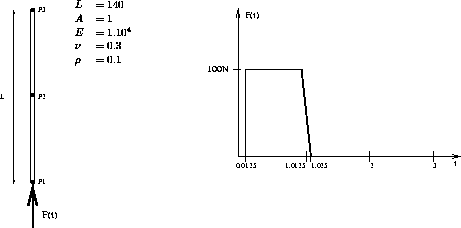
The launcher is submitted to an axial load during a limited period. Considering rigid body movements and vibration of the structure, the displacement history is searched for the bottom point.
Goal
Find the displacement history of the bottom point (P1).
Reference
J. S. Przemieniecki : Theory of matrix structural analyses (New
York : McGraw-Hill Book Co., 1968) p340.
Version
97' customer version
Model description

Results

*           Test Dyna12.dgibi: Jeux de données        *
*           ---------------------------------         *
*                                                     *
GRAPH='N';
SAUT PAGE ;
*******************************************************
*   REPONSE TRANSITOIRE D 'UNE FUSEE -METHODE DIRECT
*******************************************************
*
* DESCRIPTION DU PROBLEME
* -----------------------
*
* UNE FUSEE EST SOUMISE A UN CHARGEMENT AXIAL POUR UNE
* DUREE LIMITEE. IL S'AGIT DE TROUVER LES HISTORIQUES
* DE DEPLACEMENTS AUX EXTREMITES ET AU MILIEU DE LA
* FUSEE CONSIDERANT LE MOUVEMENT DE CORPS RIGIDE ET
* LA VIBRATION DE LA STRUCTURE .
*
* REFERENCE :
* ----------
*
* J. S. PRZEMIENIECKI,THEORY OF MATRIX STRUCTURAL
* ANALYSES (NEW YORK: MCGRAW-HILL BOOK CO.,1968)P.340
*
*******************************************************
OPTION  ECHO 0 ;
OPTIO DIME 3 ELEM SEG2 ;
*
*  MAILLAGE
*
 P1 = 0. 0. 0. ;P2 = 0. 70. 0. ;P3 = 0. 140. 0. ;
 L1 = D 1 P1 P2 ; L2 = D 1 P2 P3 ;LTOT = L1 ET L2 ;
*
*  MODELE
*
 MOD1 = MODELE LTOT MECANIQUE ELASTIQUE BARR ;
*
*  CARACTERISTIQUES MATERIELLES ET GEOMETRIQUES
*
 MAT1 = MATER MOD1 YOUN 1.E4  NU 0.3 RHO 0.1 ;
 CAR1 = CARAC MOD1 SECT 1. ;
*
*  MATRICE DE RIGIDITE
*
 RIG1 = RIGIDITE MOD1 (MAT1 ET CAR1) ;
*
*  MATRICE DE MASSE
*
 MAS1 = MASSE MOD1 (MAT1 ET CAR1)  ;
*
* CHARGEMENT
*
LI1 = PROG 0. 0.0125 1.0125 1.025  3. ;
LI2 = PROG 0. 1. 1. 0.  0.   ;
F1 = FORCE (0. 100. 0.) P1   ;
EV = EVOL MANU T LI1 F(T) LI2 ;
CHA1 = CHAR 'FORC' F1  EV ;
*
*  PREPARATION DE LA TABLE DE DONNEES POUR DYNAMIC
*
LIS1 = PROG 1.9125 2.0625  ;
TAB1 = TABLE ;
TAB1.'DEPL' = MANU CHPO LTOT 3 UZ 0. UY 0. UX 0.  ;
TAB1.'VITE' = MANU CHPO LTOT 3 UZ 0. UY 0. UX 0. ;
TAB1.'CHAR' = CHA1 ;
TAB1.'RIGI' = RIG1 ;
TAB1.'MASS' = MAS1 ;
TAB1.'FREQ' = 20. ;
TAB1.'INST' = LIS1 ;
TAB2 = DYNAMIC TAB1 ;
*
* COMPARAISON AVEC LES RESULTATS ANALYTIQUES
*
 DEP1 = TAB2 . 1 . DEPL ;
 U1 = EXTR DEP1 P1 UY ; U1TH = 10.89972 ;
 ERR1 = ((U1 - U1TH) / (ABS U1TH)) * 100. ;
 DEP2 = TAB2 . 2 . DEPL ;
 U2 = EXTR DEP2 P1 UY ; U2TH = 11.73228  ;
 ERR2 = ((U2 - U2TH) / (ABS U2TH)) * 100. ;
MESS ' DEPLACEMENT VERTICAL DE LA BASE    T= 1.9125'  ;
'MESS''THEORIE  'U1TH'CASTEM  'U1 '%ERREUR  'ERR1  ;
MESS ' DEPLACEMENT VERTICAL DE LA BASE    T= 2.0625'  ;
'MESS''THEORIE  'U2TH'CASTEM  'U2 '%ERREUR  'ERR2  ;
*
SI ((MAXI ABS (PROG ERR1 ERR2 )) < 5);
ERRE 0;
SINON;
ERRE 5;
FINSI;
FIN ;
Test dyna12 Comments
LI1 = PROG 0. 0.0125 1.0125 1.025 3. ;
LI2 = PROG 0. 1. 1. 0. 0. ;
F1 = FORCE (0. 100. 0.) P1 ;
EV = EVOL MANU T LI1 F(T) LI2 ;
CHA1 = CHAR 'FORC' F1 EV ;
The operator CHAR builds an object of type CHARGEMENT, which
contains spatial and temporal descriptions of the load :
- the spatial description is given by the object F1,
- the temporal description is given by the object EV which is
called evolution (built by the operator EVOL, EV describes the
load (object LI2) as a function of the time (object LI1)).
* INPUT DATA FOR DYNAMIC SUBROUTINE
**
LIS1 = PROG 1.9125 2.0625 ;
TAB1 = TABLE ;
TAB1.'DEPL' = MANU CHPO LTOT 3 UZ 0. UY 0. UX 0. ;
TAB1.'VITE' = MANU CHPO LTOT 3 UZ 0. UY 0. UX 0. ;
TAB1.'CHAR' = CHA1 ;
TAB1.'RIGI' = RIG1 ;
TAB1.'MASS' = MAS1 ;
TAB1.'FREQ' = 20. ;
TAB1.'INST' = LIS1 ;
TAB2 = DYNAMIC TAB1 ;
The operator DYNAMIC carries out step by step dynamic
computations, using the Newmark centered algorithm. All
required data are given in the object TAB1 defined by the
following indexes :
-'DEPL' : initial displacements,
-'VITE' : initial velocity which components are the same
as components of initial displacements,
-'CHAR' : the load (as a function of time),
-'RIGI' : the rigidity matrix,
-'MASS' : the mass matrix,
-'FREQ' : the cut off frequency which determines the time step,
-'INST' : the list of moments to save.
The value of time step will be equal to 0.25 divided by the cut off
frequency (in this case 20 Hz) which gives a step of 0.0125 sec.
DEP1 = TAB2 . 1 . DEPL ;
U1 = EXTR DEP1 P1 UY ;
DEP2 = TAB2 . 2 . DEPL ;
U2 = EXTR DEP2 P1 UY ;
The object created by DYNAMIC subroutine is a table which contains as
many tables as saved moments. Here TAB2 is composed of two tables
because the list TAB1.INST contains two moments : TAB2 . 1 and
TAB2 . 2.
Each table has three indexes :
- 'TEMP' : the value of the moment
- 'DEPL' : the displacement
- 'VITE' : the velocity
TAB2 . 1 . DEPL is a displacement field. A value
can be extracted by using EXTR operator and specifying the desired
point and the required component.