Test name
joi22
Calculation type
ISOTROPIC ELASTIC MECHANIC
Finite element type
SEG2, JOI2
Topic
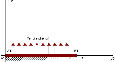
Tensile test on a 2D-joint.
The structure is a 2D-joint subjected to a tensile strength
on its upper surface, in the direction perpendicular to its plan.
It is embedded from its lower surface.
Goal
Test the JOI2 element.
Version
97' customer version
Model description

Test joi22 Results
RESULTS
Analytical solution:
From the principle of virtual work, we can show for a
one-axis tensile test that the delta displacement at
each node is equal to:
F
delta = ---------------
k * L * l
where:
F is the strength
k is the stiffness
L is the length of the joint element
l is the width of the joint element
Numerical application:
F = 100000.0 N
k = 4.2E10 N/m3
L = 2.0 m
l = 1.0 m
Delta = 100000 / (4.2E10 * 2.0 * 1.0)
= 1.190476E-6
Castem solution:


*           Test Joi22.dgibi: Jeux de données         *
*           ---------------------------------         *
*                                                     *
OPTI ECHO 0 ;
SAUT PAGE ;
MESS'!==============================================!';
MESS'!                                              !';
MESS'!                    TEST JOI22                !';
MESS'!                                              !';
MESS'!       ESSAI DE TRACTION SUR UN JOINT 2D      !';
MESS'!                                              !';
MESS'!  Un joint 2D JOI2 a son bord inferieur       !';
MESS'!  encastre.                                   !';
MESS'!  Son bord superieur est libre. Un effort de  !';
MESS'!  traction est exercé sur son bord superieur. !';
MESS'!                                              !';
MESS'!                                              !';
MESS'!  Solution analytique :                       !';
MESS'!                                              !';
MESS'!     En ecrivant le principe des travaux      !';
MESS'!  virtuels,on montre que le deplacement delta !';
MESS'!  en chaque noeud est egal, dans le cas d un  !';
MESS'!  essai de traction uniaxial, a :             !';
MESS'!                       F                      !';
MESS'!        delta = ----------------              !';
MESS'!                   k * L * l                  !';
MESS'!  ou                                          !';
MESS'!    F = force totale exercee sur la structure !';
MESS'!    k = raideur                               !';
MESS'!    L = longueur de l element joint           !';
MESS'!    l = largeur de l element joint            !';
MESS'!                                              !';
MESS'!  Application numerique :                     !';
MESS'!                                              !';
MESS'!    F = 100000.0                              !';
MESS'!    k = 4.2E10                                !';
MESS'!    L = 2.0                                   !';
MESS'!    l = 1.0                                   !';
MESS'!                                              !';
MESS'!    Delta   =  100000 / (4.2E10 * 2.0 * 1.0)  !';
MESS'!            =  1.19047619E-6                  !';
MESS'!                                              !';
MESS'!==============================================!';
OPTION DIME 2 ;
OPTION ELEM SEG2 MODE PLAN CONT  ;
*
SOLANA = 1.190476E-6 ;
SOLNUL = 0.0 ;
*
* ------- DEFINITION DE LA SURFACE TOP DU JOINT -------
*
A1 = 0.00 0.00 ;
B1 = 2.00 0.00 ;
*
* ----------          MAILLAGE          ----------
*
H1 = A1 DROIT 1 B1 ;
*
L1 = H1 ;
*
* ------ DEFINITION DE LA SURFACE BOT DU JOINT --------
*
IA1 = 0.00 0.00 ;
IB1 = 2.00 0.00 ;
*
* ----------          MAILLAGE          ----------
*
IH1 = IA1 DROIT 1 IB1 ;
*
IL1 = IH1 ;
*
* ----------   CREATION DU JOINT JOI2   ----------
*
OPTION ELEM RAC2 ;
VOL = RACCORD 0.00001 L1 IL1 ;
*
* --------- DEFINITION DES CONDITIONS LIMITES ---------
*
CL11 = BLOQ IA1 UX ;
CL12 = BLOQ IA1 UY ;
CL1 = CL11 ET CL12 ;
*
CL21 = BLOQ IB1 UX ;
CL22 = BLOQ IB1 UY ;
CL2 = CL21 ET CL22 ;
*
CL = CL1 ET CL2 ;
*
* -----    DEFINITION DU MODELE DU JOINT      ---------
*
MOD1 =MODL VOL 'MECANIQUE' 'ELASTIQUE' 'ISOTROPE' JOI2;
MA1 = MATR MOD1 KS 4.2E08 KN 4.2E10 ;
*
* -------------    MATRICE DE HOOK         ------------
*
HOO1 = HOOKE MOD1 MA1 ;
******LIST HOO1 ;
*
* ----------       MATRICE DE RIGIDITE        ---------
*
******RI1 = RIGI MOD1 MA1 ;
RI1 = RIGI MOD1 HOO1 ;
RI2 = RI1 ET CL ;
*
* ----------        FORCE DE TRACTION         ---------
*
FO1 = FORCE ( 0. 100000.0 ) L1 ;
*
* ---------            RESOLUTION            ----------
*
RE = RESO RI2 FO1 ;
MESS '                                              ' ;
MESS '                                              ' ;
MESS ' Solution Analytique :'                         ;
MESS '                                              ' ;
MESS '    UX =' SOLNUL  ;
MESS '    UY =' SOLANA  ;
MESS '                                              ' ;
MESS '                                              ' ;
MESS '                                              ' ;
MESS ' Solution Calculee :'                           ;
MESS '                                              ' ;
LIST RE ;
*
* ----------    CODE DE FONCTIONNEMENT       ----------
*
DEPA1 = EXTR RE UY A1 ;
RESI = ABS( (DEPA1-SOLANA)/SOLANA ) ;
*
SI (RESI <EG 1E-4 ) ;
   ERRE  0 ;
SINO;
   ERRE  5 ;
FINSI ;
*
* ----------     CALCUL DES DEFORMATIONS     ----------
*
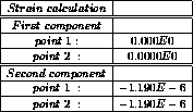
EPS1 = EPSI MOD1 RE ;
LIST EPS1 ;
*
* ----------    CALCUL DES CONTRAINTES       ----------
*
SIG1 = SIGMA MOD1 MA1 RE ;
LIST SIG1 ;
*
FIN ;
Test joi22 Comments
MOD1 = MODE VOL MECANIQUE ELASTIQUE ISOTROPE JOI2 ;
MA1 = MATE MOD1 KS 4.2E08 KN 4.2E10 ;
The JOI2 element is used in the modelling of a 2D-joint. This joint is an element with four nodes associated with the geometrical support RAC2. Within the MATE operator we should specify the shear and the normal stiffnesses, respectively KS and KN.
OPTI ELEM RAC2 ;
VOL = RACCORD 0.00001 L1 IL1 ;
The RACCORD operator enables the user to create an ordinary joint element. It generates a line VOL (MAILLAGE type) composed of double points that connects the objects L1 and IL1 (MAILLAGE type). The objects L1 and IL1 may be segments of 2 or 3 points. An element is created between an element of the L1 object and an element of the IL1 object; the distance between their points is smaller than a distance criterion (FLOTTANT type: 0.00001).
HOO1 = HOOKE MOD1 MA1 ;The HOOKE operator constructs the field of HOOKE's matrix from a field of geometrical and material properties MA1 (MCHAML type, CARACTERISTIQUES subtype). Here HOO1 is a field by element of Hooke's matrices (MCHAML type, MATRICE DE HOOKE subtype).
EPS1 = EPSI MOD1 RE ; SIG1 = SIGMA MOD1 MA1 RE ;The EPSI operator enables to calculate a strain field either from a displacement field, according to usual expressions with or without second order terms (1-st syntax), or by taking the natural logarithm of a symmetric gradient field ( 2-nd syntax). This second possibility is now available only for the massive formulation.