Test name
beton
Calculation type
ELASTIC PLASTIC MECHANICS - CONCRETE
Finite element type
CUB8
Topic
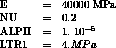
Tensile test on a cubic piece made of concrete.
The structure is an embedded cube subjected to a tensile
stress (imposed displacements). The structure follows a
concrete elastic-plastic model. The limite in tension in
the first direction for concrete (LRT1) is 4 MPa.
Goal
Test the model of concrete material for two new structures
(MMODEL and MCHAMELEM).
Reference
NAH (93/01/19)
Version
97' customer version
Model description
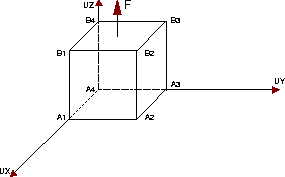
Test beton Results
CASTEM FIGURES
* Test Beton.dgibi: Jeux de données *
* --------------------------------- *
* *
* CAS TEST DU 93/01/19 PROVENANCE : NAH
OPTION ECHO 1;
GRAPH='N';
SAUT PAGE ;
*
*-----------------------------------------------------*
* *
* Exemple simple de calcul mécanique élastique *
* plastique beton fonctionnant avec les nouvelles *
* structures MMODEL et MCHAMELEM *
* *
* Un cube en béton soumis ŕ un chargement de *
* traction uniaxial suivant l'axe OZ *
* *
* La limite en traction simple du béton LTR1 est *
* égale ŕ 4 MPa *
* *
*-----------------------------------------------------*
* Définition des options
*
OPTI DIME 3 ELEM CUB8 MODEL TRIDIM ;
*opti impi 9 ;
N = 1 ;
*
* Maillage d'un cube de N*N*N éléments CUB8
*
DENS N ;
*
A1 = 0 0 0 ;
A2 = N 0 0 ;
A3 = N N 0 ;
A4 = 0 N 0 ;
B1 = 0 0 N ;
B2 = N 0 N ;
B3 = N N N ;
B4 = 0 N N ;
*
A1A2 = A1 D N A2 ;
A2A3 = A2 D N A3 ;
A3A4 = A3 D N A4 ;
A4A1 = A4 D N A1 ;
B1B2 = B1 D N B2 ;
B2B3 = B2 D N B3 ;
B3B4 = B3 D N B4 ;
B4B1 = B4 D N B1 ;
A1B1 = A1 D N B1 ;
A2B2 = A2 D N B2 ;
A3B3 = A3 D N B3 ;
A4B4 = A4 D N B4 ;
*
A1A2A3A4 = A1A2 A2A3 A3A4 A4A1 DALLE PLAN ;
B1B2B3B4 = B1B2 B2B3 B3B4 B4B1 DALLE PLAN ;
*
A1A2B2B1 = A1A2 A2B2 (INVE B1B2) (INVE A1B1)
DALLE PLAN ;
A4A3B3B4 = (INVE A3A4) A3B3 B3B4 (INVE A4B4)
DALLE PLAN ;
*
A2A3B3B2 = A2A3 A3B3 B2B3 (INVE A2B2)
DALLE PLAN ;
A1A4B4B1 = (INVE A4A1) A4B4 B4B1 (INVE A1B1)
DALLE PLAN ;
*
TOTAL = PAVE A1A2A3A4 B1B2B3B4 A1A2B2B1 A4A3B3B4
A2A3B3B2 A1A4B4B1 ;
*
*TRAC TOTAL CACH (1000 -2000 1000) ;
*
*
* Formulation, matériau défini ŕ l'aide des
* opérateurs MODL et MATR
*
MO = MODL TOTAL MECANIQUE ELASTIQUE PLASTIQUE
BETON CUB8 ;
MA = MATR MO YOUN 40000 NU 0.20 ALPH 1E-5
LTR1 4 ;
*
* Conditions de blocages
*
ENC1 = BLOQ UX A1A4B4B1 ;
ENC2 = BLOQ UY A1A2B2B1 ;
ENC3 = BLOQ UZ A1A2A3A4 ;
ENC = ENC1 ET ENC2 ET ENC3 ;
*
* Blocage pour déplacements imposés
*
* END1 = BLOQ UX A2A3B3B2 ;
* END2 = BLOQ UY A4A3B3B4 ;
END3 = BLOQ UZ B1B2B3B4 ;
* END = END1 ET END2 ET END3 ;
END = END3 ;
EN = ENC ET END ;
*
*
* Valeur des déplacements imposés
*
* FEXT1 = DEPI END1 1E-4 ;
* FEXT2 = DEPI END2 1E-4 ;
FEXT3 = DEPI END3 1E-4 ;
* FEXT = FEXT1 ET FEXT2 ET FEXT3 ;
FEXT = FEXT3 ;
*
* Force en fonction du temps
*
lt1 = prog 0. 10. ;
lt2 = prog 0. 10. ;
ev = evol rouge manu temps lt1 force lt2 ;
chat = char DIMP fext ev ;
*
* Préparation ŕ nonlin
*
ltt = prog 0 1 2 ;
tab1 = table;
tab1.blocages_mecaniques = EN;
tab1.caracteristiques = ma;
tab1.modele = mo;
tab1.chargement = chat;
tab1.temps_calcules = ltt;
pasapas tab1;
*
* Traitement des résultats
*
ptt = prog 0 ;
psz = prog 0 ;
ic = 0 ;
repeter mabou 2 ;
ic = ic + 1 ;
dd = tab1 . deplacements . ic;
ptt = ptt et ( prog ( extr dd uz b3 ) ) ;
ss = tab1.contraintes.ic ;
sz = extr ( chan chpo mo ss ) smzz b3 ;
psz = psz et ( prog sz ) ;
fin mabou ;
*
evsz = evol vert manu deplacement ptt contrainte psz ;
*dess evsz ;
*
* Code de fonctionnement
*
si ( (abs ( sz - 2. )) < 1.E-6 ) ;
erre 0 ;
sino ;
erre 5 ;
finsi ;
*
fin ;
Test beton Comments
MO = MODE TOTAL MECANIQUE ELASTIQUE PLASTIQUE
          BETON CUB8 ;
MA = MATE MO YOUN 40000 NU 0.20 ALPH 1E-5 LTR1 4 ;
In this model, the concrete behavior is non-linear in
tension, and linear everywhere else.
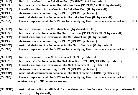
Caution : The VF1, VF2 and VF3 vectors must be orthogonal.
For computation with a tension limit different from the two others,
it is required that the vector corresponding to this limit VF1, VF2
or VF3 be defined.
When LTR1, LTR2 and LTR3 are given, both the VF1 and
VF2 vectors are required to define the directions 1, 2
and 3.
Non-zero values corresponding to initial cracks openings
in the directions 1, 2 and 3 can be introduced by means
of the TAB1 table used in the NONLIN procedure through
TAB1.'VARI'.'OUV1', TAB1.'VARI'.'OUV2',
TAB1.'VARI'.'OUV3' may be input.