Test name
dy_devo4
Calculation type
MECHANICS DYNAMICS 3D
IMPACT, LINKAGE SECTION-SECTION-OUTSIDE
Finite element type
POUT
Topic
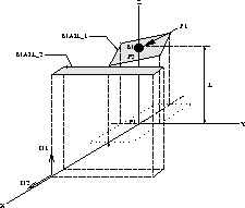
Impact of a beam with concentrated mass against a plane.
A concentrated mass is fixed at the extremity of a cantilever beam. A normal force is applied on this tips, this load gives the initial displacements of the beam.
Two different linkages are used in this example : the PROFIL_PROFIL_SECTION linkage is tested then compared with the POINT_PLAN linkage.
Goal
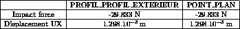
Find the impact force and displacement UX at time T = 0.4 s.
Reference
Version
97' customer version
Model description
Test dy_devo4 Results
Results (t=0.4s)
CASTEM figures
* Test Dy_devo4.dgibi: Jeux de données *
* ------------------------------------ *
* *
* si GRAPH = N, les graphiques ne sont pas affichés
* si GRAPH différent de N, tous les graphiques
* sont affichés
*
GRAPH = 'N' ;
*
SAUT PAGE ;
*
*-----------------------------------------------------*
* DY_DEVO4 *
*-----------------------------------------------------*
* *
* Tests de l'op{rateur DYNE option DE_VOGELAERE *
* _____________________________________________ *
* *
* *
* 1 poutre encastrée, 10 éléments finis, *
* masse négligeable *
* 1 masse concentrée ŕ son extrémité *
* Test PROFIL_PROFIL_EXTERIEUR avec des carrés *
* Comparaison avec la liaison POINT_PLAN *
* NB_M: nombre de segments sur le coté du carré mobile*
* NB_F: nombre de segments sur le coté du carré fixe *
* *
*-----------------------------------------------------*
OPTION ECHO 0 ;
TEMPS ;
*
NB_M = 3 ;
NB_F = 1 ;
R_PPL = 1.E+05 ;
R_PP = R_PPL ;
EXPO = 0.5 ;
*
OPTION ELEM SEG2 DIME 3 ;
*
* Définition géométrie
*
P1 = 0. 0. 0. ;
P2 = 0. 0. 0.9 ;
LIG1 = P1 D 10 P2 ;
*
* Définition matériau
*
MODL1 = MODL LIG1 MECANIQUE ELASTIQUE POUT;
MA1 = MATR MODL1 YOUNG 2.1E11 NU 0.3 RHO 78. ;
CA1 = CARB MODL1 SECT 1.1E-6 INRY 8.33E-10
INRZ 8.33E-10 TORS 5.0E-7 VECT (1. 0. 1. );
*
RIG1 = RIGI MODL1 (MA1 ET CA1) ;
MAST = (MASSE MODL1 (MA1 ET CA1)) ET
( MASSE DEPL 2.0 P2 ) ;
*
* Conditions aux limites
*
ENC1 = BLOQUE DEPL ROTA P1 ;
ENC2 = BLOQUE 'UY' LIG1 ;
RIGT = RIG1 ET ENC1 ET ENC2 ;
*
* Calcul des modes
*
MOD1=VIBRATION PROCHE ( PROG 1.0 ) RIGT MAST ;
*
* Base modale
*
TB1 = TRADUIRE MOD1 ;
TBAS = TABLE 'BASE_MODALE' ;
TBAS.'MODES' = TB1 ;
*
RIGI1 = RIGI TB1 ;
*
* Amortissement
*
AMOR1 = AMOR TBAS ( PROG 0.0 ) ;
*
TA = TABLE 'AMORTISSEMENT' ;
TA.'AMORTISSEMENT' = AMOR1 ;
*
* Déplacement initial
*
FE2 = FORCE FX 1. P2 ;
XE2 = RESOU RIGT FE2 ;
XMAX = MAXI XE2 AVEC (MOTS UX ) ;
FE1 = FE2 * (0.139E-2 / XMAX );
FGE1 = PJBA TBAS FE1 ;
ALO = RESO RIGI1 FGE1 ;
*
TINIT = TABLE 'INITIAL' ;
TINIT.'DEPLACEMENT' = ALO ;
*
*--- Définition des liaisons
*
TLIA = TABLE 'LIAISON' ;
TLB = TABLE 'LIAISON_B' ;
TLIA.'LIAISON_B' = TLB ;
NORM1 = 0 0 1 ;
*
* Liaison PROFIL_PROFIL_EXTERIEUR
*
* profil mobile
P1_1 = -0.5 0.0 0.9 ;
P1_2 = 0.0 -0.5 0.9 ;
P1_3 = 0.5 0.0 0.9 ;
P1_4 = 0.0 0.5 0.9 ;
MAIL_1 = P1_1 D NB_M P1_2 D NB_M P1_3 D NB_M P1_4 D
NB_M P1_1 ;
*
* profil fixe
P2_1 = 0.501 1.0 0.9 ;
P2_2 = 0.501 -1.0 0.9 ;
P2_3 = 0.601 -1.0 0.9 ;
P2_4 = 0.601 1.0 0.9 ;
MAIL_2 = P2_1 D NB_F P2_2 D NB_F P2_3 D NB_F P2_4 D
NB_F P2_1 ;
*
SI ( NEG GRAPH 'N' ) ;
TRAC ( 0 0 1000 ) ( MAIL_1 ET MAIL_2 ) ;
FINSI ;
*
TL1 = TABLE 'LIAISON_ELEMENTAIRE' ;
TL1.'TYPE_LIAISON' = MOT 'PROFIL_PROFIL_EXTERIEUR';
TL1.'SUPPORT' = P2 ;
TL1.'PROFIL_FIXE' = MAIL_2 ;
TL1.'PROFIL_MOBILE' = MAIL_1 ;
TL1.'NORMALE' = NORM1 ;
TL1.'RAIDEUR' = R_PP ;
TL1.'EXPOSANT_RAIDEUR' = EXPO ;
*
TLB . 1 = TL1 ;
*
*--- Définition des résultats en sortie
*
TSORT = TABLE 'SORTIE' ;
TSOR1 = TABLE 'SORTIE' ;
TSORT . 'VARIABLE' = TSOR1 ;
TSOR1 . 'DEPLACEMENT' = FAUX ;
TSOR1 . 'VITESSE' = FAUX ;
*
TSOR2 = TABLE 'SORTIE' ;
TSORT.'LIAISON_B' = TSOR2 ;
TSOR2.TL1 = VRAI ;
*
* Temps
*
PDT = 0.1E-3 ;
NP1 = 5000 ;
NINS = 5 ;
*
*------ Op{rateur DYNE ------
*
TRESU1 = DYNE 'DE_VOGELAERE' TBAS TA TINIT TSORT TLIA
NP1 PDT NINS ;
*
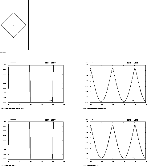
* Trac{ des courbes
*
SI ( NEG GRAPH 'N' ) ;
TITRE '***** LIAISON PROFIL_PROFIL_EXTERIEUR *****';
DESS ( EVOL MANU 'TEMPS' TRESU1 . 'TEMPS_DE_SORTIE'
'FN' TRESU1 . TL1 . 'FORCE_DE_CHOC')
'MIMA' ;
*
DESS ( EVOL MANU 'TEMPS' TRESU1 . 'TEMPS_DE_SORTIE'
'UX' TRESU1 . TL1 . 'UX' ) 'MIMA';
FINSI ;
D_FC_1 = EXTRAIRE ( TRESU1 . TL1 . 'FORCE_DE_CHOC' )
801 ;
D_DE_1 = EXTRAIRE ( TRESU1 . TL1 . 'UX' ) 801 ;
*
SAUT PAGE ;
MESS '-----> liaison PROFIL_PROFIL_EXTERIEUR' ;
MESS ' valeur de la force de choc :' D_FC_1 ;
MESS ' valeur du déplacement :' D_DE_1 ;
*
* Liaison POINT_PLAN
*
NORM1 = 1 0 0 ;
TL1 = TABLE 'LIAISON_ELEMENTAIRE' ;
TL1.'TYPE_LIAISON' = MOT 'POINT_PLAN' ;
TL1.'SUPPORT' = P2 ;
TL1.'NORMALE' = NORM1 ;
TL1.'RAIDEUR' = R_PPL ;
TL1.'JEU' = 0.001 ;
*
TLB . 1 = TL1 ;
TSOR2.TL1 = VRAI ;
*
TRESU2 = DYNE 'DE_VOGELAERE' TBAS TA TINIT TSORT TLIA
NP1 PDT NINS ;
*
* Tracé des courbes
*
SI ( NEG GRAPH 'N' ) ;
TITRE '***** LIAISON POINT_PLAN *****' ;
DESS ( EVOL MANU 'TEMPS' TRESU2 . 'TEMPS_DE_SORTIE'
'FN' TRESU2 . TL1 . 'FORCE_DE_CHOC') 'MIMA' ;
*
DESS ( EVOL MANU 'TEMPS' TRESU2 . 'TEMPS_DE_SORTIE'
'UX' TRESU2 . TL1 . 'UX' ) 'MIMA' ;
FINSI ;
*
TEMPS ;
*
* Code de bon fonctionnement
*
D_FC_2 =EXTRAIRE ( TRESU2 . TL1 . 'FORCE_DE_CHOC' ) 801;
D_DE_2 =EXTRAIRE ( TRESU2 . TL1 . 'UX' ) 801 ;
SAUT 2 LIGNES ;
MESS '-----> liaison POINT_PLAN ' ;
MESS ' valeur de la force de choc :' D_FC_2 ;
MESS ' valeur du déplacement :' D_DE_2 ;
SAUT 3 LIGNES ;
R_FC = ABS ( ( D_FC_1 - D_FC_2 ) / D_FC_2 ) ;
R_DE = ABS ( ( D_DE_1 - D_DE_2 ) / D_DE_2 ) ;
SI ( ( R_FC <EG 1E-2 ) OU ( R_DE <EG 1E-2 ) ) ;
ERRE 0 ;
SINON ;
ERRE 5 ;
FINSI ;
*
FIN ;
Test dy_devo4 Comments
TB1 = TRADUIRE MOD1 ;
TBAS = TABLE 'BASE_MODALE' ;
TBAS.'MODES' = TB1 ;
The DYNE operator uses a BASE_MODALE subtype table but the VIBR operator creates a SOLUTION object if keyword TBAS is not specified. Also it is necessary to create a BASE_MODALE subtype table from a SOLUTION object of MODE subtype.
First of all, the TRADUIRE operator creates a BASE_DE_MODES subtype table (TB1) from a SOLUTION object (MOD1). After the creation of a BASE_MODALE subtype table (TBAS), TB1 is given in TBAS.'MODES'.
RIGI1 = RIGI TB1 ;
RIGI1 is the stiffness due to the modes contained in TB1 (BASE_DE_MODES subtype table) .
FGE1 = PJBA TBAS FE1 ;
ALO = RESO RIGI1 FGE1 ;
ALO is a CHPOINT object which has only one component (ALPHA) . Indeed this object was created with FGE1 load (of modal component) and RIGI1 (generalized stiffness).
TL1 = TABLE 'LIAISON_ELEMENTAIRE' ;
TL1.'TYPE_LIAISON' = MOT 'PROFIL_PROFIL_EXTERIEUR' ;
TL1.'SUPPORT' = P2 ;
TL1.'PROFIL_FIXE' = MAIL_2 ;
TL1.'PROFIL_MOBILE' = MAIL_1 ;
TL1.'NORMALE' = NORM1 ;
TL1.'RAIDEUR' = R_PP ;
TL1.'EXPOSANT_RAIDEUR' = EXPO ;
TLB . 1 = TL1 ;
The linkage PROFIL_PROFIL_EXTERIEUR is used for impacts of a moving section onto a fixed section.
The moving section (TL1.'PROFIL_MOBILE') is connected to the structure by a point (TL1.'SUPPORT') and is outside the fixed section (TL1.'PROFIL_FIXE'). The sections must be oriented anti clockwise and in rest position both the mesh sections must have any intersection point.
The given normal (TL1.'NORMALE', N1 in the model description) must be perpendicular to the plane composed by both sections.
The normal impact force F is given by : 
where K is the impact stiffness (TL1.'RAIDEUR'),
A is the section surface which passed through fixed section,
b is the stiffness exponent (TL1.'EXPOSANT_RAIDEUR').
To obtain the same configuration as the PROFIL_PROFIL_EXTERIEUR linkage, the value of the gap must be equal to 0.001 (the gap along X-axis between moving section and fixed section was of 0.001 too) and the normal must be oriented along X-axis (N2 in the model description).