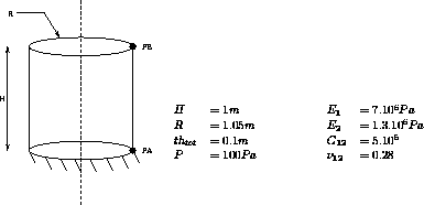
 ). The cylinder is subjected
to an internal pressure. The displacements of its bottom end are constrained along the Z
axis.
Test name
comp1
Calculation type
MECHANICS COMPOSITE 3D
Finite element type
DKT
Topic
A two layer composite cylinder subjected to internal pressure.
The cylinder fibers are wound around the Z-axis ( ). The cylinder is subjected
to an internal pressure. The displacements of its bottom end are constrained along the Z
axis.
In order to reduce the number of freedom degrees, one of the top nodes is forced to move along X and Y-axis and in rotation around Z-axis (node PB).
The pressure is perpendicular to the internal surface of the cylinder.
Goal
Find the radial displacement of the point PA (1.05, 0, 0) belonging to the bottom of
the cylinder.
Reference CASTEM
Report CEA-DMT 89/184 : Modélisation des composites de type multi-couches dans
CASTEM 2000.
Version
97' customer version
Model description

Test comp1 Results
Results

CASTEM figures

*           Test Comp1.dgibi: Jeux de données         *
*           ---------------------------------         *
*                                                     *
* SI GRAPH = N PAS DE GRAPHIQUE AFFICHE
* SINON SI GRAPH DIFFERENT DE N TOUS LES
* GRAPHIQUES SONT AFFICHES
*
GRAPH = 'N';
*
SAUT PAGE ;
*SI (NEG GRAPH 'N') ;
*  OPTION ECHO 1 ;
*SINO ;
*  OPTION ECHO 0 ;
*FINSI ;
*******************************************************
*                CYLINDRE COMPOSITE BICOUCHE
*           FIBRES ENROULEES -45/+45 AUTOUR DE L'AXE
*                     PRESSION INTERNE
*
*
* Un cylindre bloqué à sa base en déplacement suivant
* l'axe Z est soumis à une pression interne.
*
* Afin de réduire le nombre de degrés de liberté,
* un noeud du sommet est bloqué en translation suivant
* X et Y et en rotation suivant Z (noeud PB).
*
* La pression est normale à la surface interne
* du cylindre.
*
* Le déplacement radial d'un noeud de la base est
* comparé à celui que l'on obtiendrait par méthode
* analytique : 1.3776E-4
*
*******************************************************
TITRE
'CYLINDRE COMPOSITE BICOUCHE SOUS PRESSION INTERNE';
OPTION DIME 3 ELEM TRI3 MODE TRIDIM ;

TEMPS ;
DENS 0.1 ;
*______________________________________________________
*   GEOMETRIE
*______________________________________________________
R = 1.05 ; H = 1. ;
PA = R 0. 0.  ; PB = R 0. H ;
O1 = 0. 0. 0. ; O2 = 0. 0. H ;
NR1 = 1. 1. 0. ;
LI1 = PA D 4 PB ;
CYLP = ROTA LI1 8 90 O1 O2 ;
CYL1 = ORIENTER CYLP NR1 ;
CYL2 LIB = TOURNER CYL1 LI1 90 O1 O2 ;
CYL3 LIC = TOURNER CYL2 LIB 90 O1 O2 ;
CYL4 LID = TOURNER CYL3 LIC 90 O1 O2 ;
CYL = CYL1 ET CYL2 ET CYL3 ET CYL4 ;
ELIM CYL ;
OEIL = 10. 10. 5. ;
*
SI (NEG GRAPH 'N') ;
  TRACE OEIL CACH CYL ;
FINSI ;
*
MODORT = MODL CYL MECANIQUE ELASTIQUE ORTHOTROPE DKT ;
*

*______________________________________________________
*   DESCRIPTION DU MATERIAU ORTHOTROPE ET
*   CREATION DE LA RIGIDITE DE LA COUCHE 1
*______________________________________________________

MAT1 = MATR MODORT DIRE O2 INCL 45 NR1 YG1 7E6 YG2
       1.3E6 NU12 0.28 G12 5E5 ;
CAR1 = CARB MODORT EPAI 0.05 EXCENTREMENT 0.025 ;
MAT1=MAT1 ET CAR1;

RIG1 = RIGI MODORT MAT1  ;
*______________________________________________________
*   DESCRIPTION DU MATERIAU ORTHOTROPE ET
*   CREATION DE LA RIGIDITE DE LA COUCHE 2
*______________________________________________________
MAT2 = MATR MODORT DIRE O2 INCL -45 NR1 YG1 7E6 YG2
       1.3E6 NU12 0.28 G12 5E5 ;

CAR2 = CARB MODORT EPAI 0.05 EXCENTREMENT -0.025 ;
MAT2=MAT2 ET CAR2;
RIG2 = RIGI MODORT MAT2  ;
*______________________________________________________
*______________________________________________________
CO1 = COTE 2 CYL1 ; CO2 = COTE 2 CYL2 ;
CO3 = COTE 2 CYL3 ;
CO4 = COTE 2 CYL4 ;
COB = CO1 ET CO2 ET CO3 ET CO4 ;
CDL1 = BLOQ UZ COB ;
CDL2 = BLOQ UX UY RZ PB ;
CDL = CDL1 ET CDL2 ;
*______________________________________________________
*   CALCUL
*______________________________________________________
RIGITOT = RIG1 ET RIG2 ET CDL ;
FP = PRES COQUE MODORT 100. NORM ;
DEPL = RESO RIGITOT FP ;
*______________________________________________________
*______________________________________________________
DEFO1=DEFO CYL DEPL;
DX=EXCO DEPL UX;
SI (NEG GRAPH 'N') ;
 TRAC OEIL CACH DEFO1 DX;
FINSI;
*
D = EXTR DEPL UX PA ;
SAUT PAGE ;
MESS ' DEPLACEMENT RADIAL EN PA DE REFERENCE
:    1.37762E-4 ' ;
SAUT 1 LIGN ;
MESS ' DEPLACEMENT RADIAL EN PA CALCULE
:   ' D ;
SAUT 2 LIGN ;
TEMPS ;
*                    CODE BON FONCTIONNEMENT
DEPREF=1.37762E-4;
RESI=ABS((D-DEPREF)/DEPREF);
SI (RESI <EG 1E-2);
   ERRE 0 ;
SINO;
   ERRE 5 ;
FINSI ;
FIN;
Test comp1 Comments
MAT1 = MATER MODORT1 DIRE O2 INCL 45 NR1 YG1 7E6 YG2 1.3E6 NU12 0.28 G12 5E5 ; The orthotropy is defined by the first orthotropic direction. First, a reference vector VEC1 is defined, thus giving the first orthotropic direction.
- Reference vector VEC1

- First orthotropic direction

CAR1 = CARAC MODORT1 EPAI 0.05 EXCENTR 0.025 ; The median line of the layer 1 is 0.025 meters (=EPAI/2) away from the median line of the cylinder (R = 1.05).
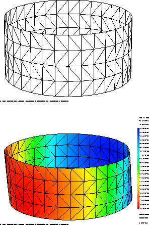
TRAC OEIL CACH DEFO1 DX; It is possible to plot the isodisplacements or isostrains on the deformed shape. For this, the object DEFO1 (DEFORME type) must be added in the TRAC operator.
